


")

 (1)")

Stanley Parker is credited for being the engineer behind the development of the GD&T system in 1938. Before that, all features used only X-Y axes to determine the position of a hole. GD&T symbols are used to specify the allowable variations in form, size, orientation, and location of features on a part or assembly
Unraveling GD&T Symbols
Geometric Dimensioning and Tolerancing (GD&T) symbols, essential for ensuring the accuracy and reliability of engineering designs. This guide illuminates the significance of GD&T symbols in communicating tolerances effectively, empowering engineers to achieve unparalleled precision in manufacturing.
One of the most important aspects of GD&T symbols is that they communicate the designer’s intent clearly and understandable. Unlike traditional dimensional tolerancing, which focuses on specifying sizes and locations, GD&T focuses on the function of the features.
What is GD&T symbol : GD&T stands for Geometric Dimensioning and Tolerance, is a set of symbols used by engineers to give a set of manufacturing information or instruction to their production team. its uses a symbolic language ON engineering drawing and its allowable variation normally. GD & T is done based on ASME American Society Mechanical Engineers Standard.
Why use GD&T symbols :GD&T symbols are far more better and accurate than following the traditional tolerance. This works better when both the designing team and manufacturing team are well versed in reading and interpreting these symbols. GD&T also helps in the perfect assembly of the parts with 100% accuracy and not only that but also another crucial benefit of GDT is that it saves time.
GD&T symbols
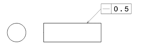
Straightness is the most fundamental form control which is used to control the surface variations from the highest peaks to lowest troughs for each line segment on the surface .
Orientation geometric control is applied when the angle between a reference face and another face needs to be controlled.Angularity is commonly applied to do this as shown where the targeted surface is being controlled in terms of its angle with respect to a datum A
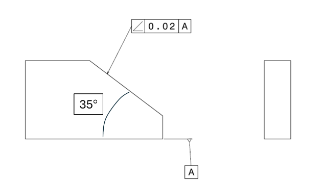
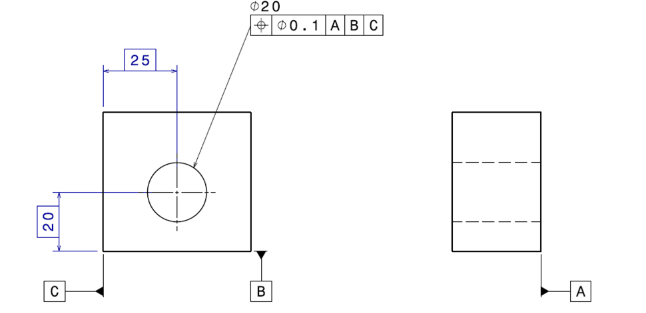
There is always a datum referred to an orientation control. Minimum one datum is mandatory , there can be more than one. The most commonly used symbols and geometric control is the true position control. Position cannot be used on plane surfaces , only on features of size.
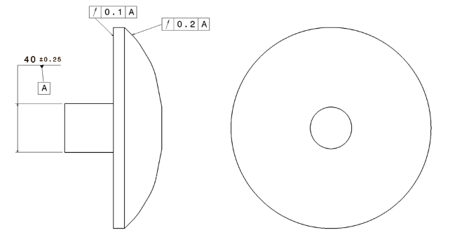
It is a geometric control primarily for rotating surfaces. Any surface which is rotating about an axis uniformly can be measured in terms of its runout. Circular runout like circularity controls each cross section or circular element and total runout controls the complete surface whether cylindrical or flat

Profile of a line describes a tolerance zone around any line in any feature, usually of a curved shape. Profile of a line is a 2-Dimensional tolerance range that can be applied to any linear tolerance.
Conclusion:
Mastering GD&T symbols is essential for engineers striving to achieve precision and reliability in their designs. By understanding and applying GD&T principles effectively, you can optimize manufacturing processes, improve product quality, and drive innovation in your industry. Embrace the power of GD&T symbols to elevate your engineering projects to new heights of excellence.
About Millwright:
Elevate your machining skills at our CNC training center in Chennai, where we seamlessly integrate GD&T principles. With expert-led instruction and hands-on practice, master precision engineering for a thriving career in manufacturing. Join us and unlock opportunities in the ever-evolving world of CNC machining.


