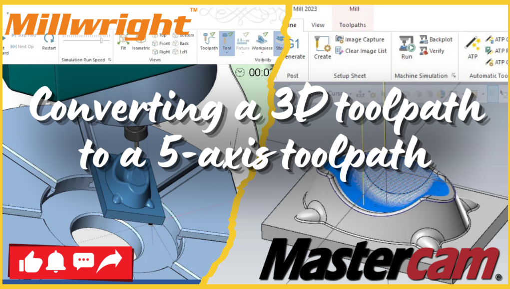
Introduction: In the world of CNC machining, leveraging the power of 5-axis machining can significantly enhance precision and efficiency, especially when dealing with complex geometries. In this guide, we’ll walk you through the process of converting a 3D toolpath to a 5-axis toolpath in Mastercam. Whether you’re working with 3D roughing, finishing, or high-speed surface toolpaths, these steps will help you optimize your machining process.
Step 1: Create or Import Your 3D Toolpath The journey begins by creating a 3D toolpath in Mastercam or importing an existing one. Common 3D toolpaths include 3D High Speed Surface, Contour, or Parallel toolpaths. These form the foundation of your machining strategy, providing the initial paths that will be adapted for 5-axis machining.
Step 2: Understand the Geometry Before diving into the conversion, it’s crucial to understand the geometry you’re working with. Ensure that the surfaces are complex and multi-angled, as these characteristics are where 5-axis machining truly shines. Proper geometry analysis will help you make informed decisions during the conversion process.
Step 3: Select the Toolpath to Convert Navigate to the Toolpath Manager in Mastercam and select the 3D toolpath you wish to convert. This selection sets the stage for transforming your standard toolpath into a sophisticated 5-axis operation.
Step 4: Convert to a 5-Axis Toolpath
- Right-Click on the Toolpath: In the Toolpath Manager, right-click on the selected toolpath.
- Select ‘Edit’ or ‘Post’: Depending on your version of Mastercam, choose the appropriate option to edit or post the toolpath.
- Choose 5-Axis Options: Look for the settings to convert or adjust the toolpath for 5-axis machining. These might be found under a specific section for advanced or 5-axis options.
Step 5: Adjust Toolpath Parameters After converting the toolpath, fine-tuning is essential. Adjust parameters such as tool angles, feed rates, and tool orientation to ensure optimal performance in 5-axis machining. This step is key to maximizing the benefits of the conversion.
Step 6: Define the 5-Axis Setup
- Tool Orientation: Define the correct orientation of the tool relative to the part. Set up the angles necessary for the tool to approach the surface efficiently.
- Workplane and Coordinate System: Ensure the workplane and coordinate system are accurately defined for 5-axis operations. This alignment is critical for precise machining.
Step 7: Simulate the Toolpath Utilize Mastercam’s powerful simulation tools to verify the 5-axis toolpath. Check for any potential collisions, tool path deviations, or issues with the setup. Simulation helps prevent costly errors during actual machining.
Step 8: Post-Process the Toolpath With the toolpath ready, the next step is to post-process it to generate the G-code for your 5-axis machine. Ensure you use a post-processor that matches your machine’s configuration, as this will directly impact the success of the operation.
Step 9: Verify and Test Finally, verify the G-code and, if possible, test the toolpath on a virtual machine or the actual machine itself. This verification step is crucial to ensure everything functions as expected, preventing errors and optimizing the machining process.
Conclusion: Converting a 3D toolpath to a 5-axis toolpath in Mastercam opens up a world of possibilities in CNC machining. By following these steps, you can ensure that your toolpaths are optimized for the complexities of 5-axis operations, leading to more efficient and precise machining outcomes.
CNCMachining #Mastercam #5AxisMachining #CADCAM #ManufacturingExcellence #CNCProgramming
3D toolpath, 5-axis toolpath, Mastercam, CNC machining, toolpath conversion, 5-axis machining, CAD/CAM software


